Head Pose
Head Pose Database | Database Building | Data | ICME 05 Set Up | People

Description
In October 2003 a head pose video database was built at the Idiap research institute . The objective was to construct a video database allowing to perform quantitative evaluation of algorithms extracting information related to the head pose of people, such as head tracking and pose estimation algorithms, or focus of attention analysis. Such a database did not exist before (at least publicly). By making our database publicly available to researchers, rigorous algorithm comparisons will be allowed.
The database comprises two sets of video involving people engaged in natural activities. In the first one, people are participating in meetings and are debating statements displayed on a screen. In the second set, persons are performing some tasks in their office. In all cases, the head pose of people is continuously annotated thanks to the use of a 3D location and orientation magnetic trackers called flock of birds. In both sets, the head pose of 16 different persons has been recorded.
This database building was done in the context of two projects.
- The first one is the Multi-Object, Multi-Camera Tracking and Activity Recognition (MUCATAR) project which is aimed at developping probabilistic algorithms for joint people tracking and activity recognition. The MUCATAR project is funded by the swiss National Center of Competence in Research (NCCR) on Interactive Multimodal Information Management (IM)2 which is devoted to the advancement of research, and the development of prototypes, in the field of man-machine interaction.
- The second project is AMI (Augmented Multi-party Interaction), an EC IST funded projects which targets the advancement of computer enhanced multi-modal interaction in the context of meetings.
Database Building

Recording Set Up
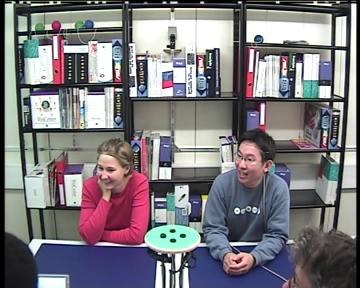
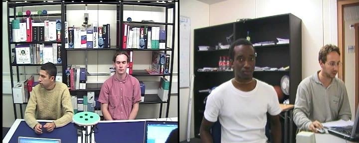
Two common indoor environments were selected for our database: a meeting room (left image) and an office (right image). The two set ups were the following.
- in the meeting case, four persons were engaged in a debate about statements displayed on a screen (at the left in the image example). However, due to sensor limitations (range or reliable recordings), the head pose of only two of them (visible in the camera view, left image) were being recorded. The scenario of the meetings was the following. First the two persons whose pose was recorded had to look straight at the camera to define their frontal view (see below). Then they had to write their name on a sheet of paper, and finally, for the remaining of the recording they had to discuss statements displayed on the projection screen with the other participants.
- for the office recording, only the pose of the person nearest to the camera (see right image) was recorded. The scenario of he recording was the following. The person had to look straight at the camera to define his frontal head pose and perfom alignment gestures (sudden pan and tilt head rotations). Then he had to look at specific point of the office and to follow the instructions of the experimenter.
In the following, we describe the main elements to obtain the pose annotation. More details can be found in the following report.
Head Pose Definition and Annotation
In our data, the annotated head pose was defined relatively to the camera 3D basis and a reference head pose called frontal pose. First, a 3D reference coordinate system is rigidly attached to the head, with the following basis axes: the x axis is defined by the line between the two eyes, the y axis is defined by the vertical line going through the nose in a frontal view of the face, and the z axis is orthogonal to the x and y axis. Additionally, the head in an image is said to be in a frontal pose when it's head reference basis is aligned to the 3D camera reference basis at the head image position. Given these definitions, the annotated head pose of a viewed head is defined by the Euler angles parameterizing the rigid transformation allowing to pass from the virtual frontal head basis configuration to the real head configuration of the viewed head in the current image.
Several euler decompositions can be exploited. In the most common one, however, the rotation angle around the y axis is called the head pan, the rotation angle around the x axis is called the head tilt and the rotation angle around the z axis is called the head roll. The initial head pose labeling was done using a magnetic sensor called flock of bird (FOB) from Ascension Technology. The FOB is composed of two components: a reference base (usually fixed on the table), and the birds, that we rigidly tied to the head. The FOB device then outputs the Euler angles of the bird relatively to its reference basis. To obtain the head pose annotated as described above, two transformations involving calibration were necessary:
- the first one consisted in transforming the bird pose, measured in FOB reference base, into a bird pose measured in the camera reference coordinate frame, which requested the knowledge of the rigid transform from the FOB reference frame to the camera reference frame.
- the second transformation was necessary to align the bird coordinate frame axes with whose of the head reference frame. This was done by exploiting the bird measurements of a person looking straight at the camera, i.e being in frontal configuration.
Aligning FOB and Video Frames
Because the starting time of the FOB and the video recordings were different, we needed to first align the FOB and video data. This was achieved by identifying the timestamps of sudden changes of head poses in both modalities. By extracting several timestamps corresponding pairs, we were able to precisely estimate the time offset between the two recordings.
Meeting Room Data
Each recording in the meeting room always involves two persons sitting in front of the camera. The person to the right of the image will be labeled RightPerson and the person to the left will be labeled LeftPerson. The data of these recordings are stored in 8 directories MEETING1,...,MEETING8. Each directory MEETING[MeetingNum] (MeetingNum=1,...,8) contains:
- the video sequence: VideoMeet[MeetingNum].avi
- the raw flock outputs (thus, in Flock of birds reference coordinate system): LeftFOBDataMeet[MeetingNum].mat for the person to the left and RightFOBDataMeet[MeetingNum].mat for the person to the right.
- the intrinsic camera parameters: CamParamIntMeet.mat
- the calibration parameters between the flock of bird and the camera: FlockCamCalibParamMeet.mat
- two files containing the aligned data for the right and left person: AlignedRightDataMeet[MeetingNum].mat and AlignedLeftDataMeet[MeetingNum].mat. Each of them contains a structure data with the following fields:
- data.VideoFrames: video_num=data.VideoFrames(k) provides the image number video_num associated with the flock measurement k. Note that as recording of the video began before the recording of the flock and ended after, some of the first and last frames of the video do not correspond to any flock measurements.
- data.AngCam(k,1:3): contains the head pose euler angles
- data.AngCam(k,1) is the head pan
- data.AngCam(k,2) is the head tilt
- data.AngCam(k,3) is the head roll.
- data.FlockLocation3D(k,1:3): contains the 3D location measurement of the flock in the camera basis.
- data.FrameFlockLocation(k,1:2): contains the pixel location of the flock in the image.
- data.valid: is an array of boolean. data.valid(k) is 1 if the FOB recording of the video frame data.VideoFrames(k) is valid and zero otherwise.
Office Data
The recordings in the office involved 15 people, one per recording. The Data of these recordings are stored in the directories OFFICE01,...OFFICE15. However, as all the necessary calibration have not been done yet, these are unavailable now. If you still want these recordings, please email us (see contacts)
Video Frames Extraction
The video frames of the recordings were extracted using mplayer. Given a movie my_movie.avi the command line is:
mplayer -ss 00:00:00 -vo jpeg -vf scale=360:288 my_movie.avi
this command extract all the jpg image frames of my_movie.avi in the current folder at a resolution 360:288.
ICME 05 Set Up
Head Pose Tracking Algorithms Evaluation
In our paper
Evaluation of Multiple Cues Head Pose Estimation Algorithms in Natural Environments
Sileye Ba and Jean-Marc Odobez [pdf file]
in Proceedings of the International Conference on Multi-media & Expo (ICME), Amsterdam, 2005
We ran experiments to compare two classes of head pose tracking algorithm: a first class where the head tracking and the pose estimation are performed one after the other, and a second class where the head tracking and pose estimation are optimized jointly. The evaluation data and the errors measures are given in the following.
Evaluation Data:
The tracking evaluation protocol is the following. For our experiments we use half of the persons of the meeting database as train set to train pose dynamic model and the half remaining persons as test set to evaluate the tracking algorithms. In each one of the recording of the 8 persons of the test set, we selected 1 minute of recording (1500 video frames) for evaluation data. We decided to use only one minute to save machine computation time, as we use a quite slow matlab implementation of our algorithms. Video frames corresponding to training and test data are given in the following table:
|
Traning Data |
Test Data |
||
| Recording | Video Frames | Recording | Video Frames |
| Meeting 3 L | 6001-7500 | Meeting 1 R | 1-1500 |
| Meeting 4 L | 13501-15000 | Meeting 1 L | 4051-6000 |
| Meeting 5 L | 13501-15000 | Meeting 2 R | 1501-3000 |
| Meeting 6 R | 12001-13500 | Meeting 2 L | 6001-7500 |
| Meeting 6 L | 7501-9000 | Meeting 3 R | 9001-10500 |
| Meeting 7 R | 6001-7500 | Meeting 4 R | 9001-10500 |
| Meeting 7 L | 18001-18500 | Meeting 5 R | 9001-10500 |
| Meeting 8 R | 7501-9000 | Meeting 8 L | 16501-18000 |
Errors Measures:
In this paragraph, we define the head pose estimation error measures used to evaluate tracking performances. A head pose defines a vector in the 3D space, the vector indicating where the head is pointing at. It can be thought of as a vector based on the center of the head and passing through the nose. It is worth noticing that in the Pointing representation, this vector depends only on the head pan and tilt angles. The angle between the 3D pointing vector defined by the head pose ground truth (GT) and the head pose estimated by the tracker can be used as the first pose estimation error measure. In order to have more details about the origins of the errors we will also measure the individual errors made separately on the pan, tilt and roll angles measured in the Pointing representation. For each one of the four error measures, we compute the mean, standard deviation, and median value of the absolute value of the errors. These set of errors measures can be computed using functions available in the folder ROUTINES of the database (HeadPosetrackingErr.m).
People
For information about the database, please contact:
![]() Dr Jean Marc Odobez, Senior Researcher
Dr Jean Marc Odobez, Senior Researcher